In life we're used to dealing with decimal numbers ("real" numbers as one of my friends put it) but computers only deal with 0's and 1's, which then compose a binary number system. Luckily, binary digits and decimal digits work about the same. Each digit in a decimal number represents a multiple of some power of 10. Like: 600 = 6*100 = 6*102. The rightmost decimal digit (still to the left of the decimal point) represents a multiple against 100 = 1, the next digit to the left is a multiple of 101, the next to the left is a multiple of 102, etc. (Remember, in CS we usually start counting with 0 instead of 1).
Similarly, each binary digit gives a multiple of a power of 2. So the rightmost digit is a multiple of 20 = 1, the next one to the left is a multiple of 21 = 2, etc. In the exercises below we'll practice converting between binary numbers and decimal numbers. The table below gives the decimal value of the first few powers of 2.
| Power of 2 | Decimal Value | Power of 2 | Decimal Value |
|---|---|---|---|
| 20 | 1 | 27 | 128 |
| 21 | 2 | 28 | 256 |
| 22 | 4 | 29 | 512 |
| 23 | 8 | 210 | 1024 |
| 24 | 16 | 211 | 2048 |
| 25 | 32 | 212 | 4096 |
| 26 | 64 | 213 | 8196 |
Question 1(A): Convert the following binary numbers into the equivalent decimal value.
Question 1(B): Convert the following decimal numbers into the equivalent binary number.
Question 1(C): Describe an algorithm that, given a binary number, could produce the equivalent decimal number. Try to make your description as close to Java code as possible, but don't worry about having perfect syntax. If necessary, you can resort to describing steps in English.
In lecture we were introduced to the idea of using the binary digits of 0 and 1 as the boolean values false and true. For these boolean values we can also have variables - just like with the variables we used in our Java programming. When writing these variables in a logical statement these variables are combined using the operators logical AND (*), logical OR (+), and logical NOT (! or a bar over the negated statement).
For a given logical variable A there are two different ways it can be written: A or A. The first statement is true if the variable A holds the value of 1 (used to represent true). The second statement is negated, so it is true if the variable A holds the value of 0 (used to represent false).
Question 2(A): Given the following values for the given variables, determine if the statements below resolve to true or to false.
A = 1, B = 1, C = 0, D = 0
Truth tables are a useful tool when working with boolean expressions. A truth table says, given any possible input, what the resulting output should be. Here's an example expression and its equivalent truth table. Expression: A*!B + !A*B
| Input A | Input B | Output |
|---|---|---|
| 0 | 0 | 0 |
| 0 | 1 | 1 |
| 1 | 0 | 1 |
| 1 | 1 | 0 |
Question 3(A): For the boolean expressions below, write out a truth table showing outputs equivalent to what the expression gives.
| Input A | Input B | Input C | Output |
|---|---|---|---|
| ______ | ______ | ______ | ______ |
| ______ | ______ | ______ | ______ |
| ______ | ______ | ______ | ______ |
| ______ | ______ | ______ | ______ |
| ______ | ______ | ______ | ______ |
| ______ | ______ | ______ | ______ |
| ______ | ______ | ______ | ______ |
| ______ | ______ | ______ | ______ |
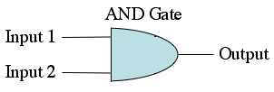
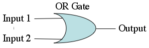
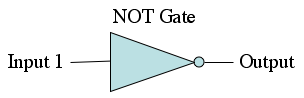
Remember also that we can also express these boolean statements as circuits using the AND gate, OR gate, and the NOT gate. Here are all of the gates pictured below.
Question 3(B): For each of the given truth tables below, draw a circuit using AND, OR, and NOT gates to represent it. A good way to go about doing this is by using the OR'ing of AND's technique. First, design a separate circuit for each input case where the the circuit should return true. Each of these circuits should be designed to return true only when it's specific case somes up (using AND gates). Next, combine the outputs of all of those truth circuits using OR gates. In this way you have one large circuit that returns true whenever the truth table does.
| Input A | Input B | Input C | Output |
|---|---|---|---|
| 0 | 0 | 0 | 0 |
| 0 | 0 | 1 | 1 |
| 0 | 1 | 0 | 0 |
| 0 | 1 | 1 | 0 |
| 1 | 0 | 0 | 0 |
| 1 | 0 | 1 | 0 |
| 1 | 1 | 0 | 0 |
| 1 | 1 | 1 | 1 |
| Input A | Input B | Input C | Output |
|---|---|---|---|
| 0 | 0 | 0 | 0 |
| 0 | 0 | 1 | 0 |
| 0 | 1 | 0 | 0 |
| 0 | 1 | 1 | 1 |
| 1 | 0 | 0 | 0 |
| 1 | 0 | 1 | 1 |
| 1 | 1 | 0 | 0 |
| 1 | 1 | 1 | 1 |
Finally, we can find that, while the OR'ing of AND's technique is quite useful and a great starting point, we can often simplify the expressions it gives. Here a few simple resolution rules.
The last two rule are known as De Morgan's laws, which were invented by the mathematician Augustus De Morgan.
Question 4: Use the rules above to simply the boolean expressions below. (The only logical variables involved are A, B, C, and D. If any of the 4 variables are missing from the expression, you can treat the expression as if the missing variable did not exist.) Note that you could write a truth table for the initial expression, and for your final expression if you wanted to be certain that both statements were equivalent.